Cylinders and cylinder liners Part 1
Information on diagnostics
Why is there a vertical crack running from the cylinder liner flange? What is the reason why the liner flange is completely detached? How do you use ink to check for deformation of the liner flange contact surface? Where does the cavitation on the cylinder liner come from? This article gives you the answers.
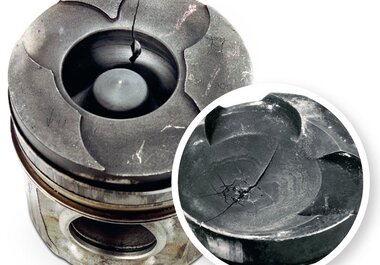
Longitudinal cylinder liner cracks
- Vertical crack, extending from the liner flange.
- Dry cylinder liners can also be affected because of their relatively thin cylinder wall thickness.
Damage assessment
Cracks of this nature are frequently caused by careless handling of the cylinder liners (as a result of impacts or blows). Even if the cylinder liner does not suffer visible damage straight away, a microscopic crack or notch can generate a fracture during subsequent operation of the engine. Incorrect liner flange seat surfaces and dirt between the cylinder liner and the cylinder block can also cause this type of damage. In the case of longitudinal cracks caused by faulty liner flange seating surfaces, the longitudinal cracks often occur in conjunction with lateral cracks.
Possible causes for the damage
- Cracks or notches due to improper handling of the cylinder liners during transport or repairs.
- Hydraulic locks.
- Foreign bodies underneath contact or sealing surfaces.
- Faulty flange seat (refer to the chapter entitled “Torn-off flange on the cylinder liner”).
- Material erosion on edge of the cylinder liner through knocking combustion and consequent weakening of the cylinder liner.
Torn-off flange on the cylinder liner
- Liner flange has been torn off.
- The flange crack starts at the base of the bottom edge of the liner flange and extends upwards at an angle of approx. 30°.
Damage assessment
This type of damage is caused by bending moments that arise as a result of improper installation (dirt/form defects). In most cases, the cylinder liner flange is already pressed off when the cylinder head is tightened down. On the latest generations of engines for commercial vehicles with pump-nozzle unit or common rail fuel injection systems, the engine block is subjected to increasing loads as a result of the increasing combustion pressures. The use of very hard steel cylinder head gaskets on these engine types can cause distortion of the crankcase in the area of the liner flange seating surface after the engine has been in operation for a long time.
Note
 |
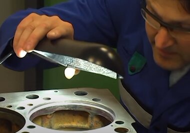
The distortion of the seating surface cannot be detected by visual inspection alone unless the appropriate measuring aids are used. One simple way to check for this distortion is the use of bearing ink: thinly apply the ink around the seating surface of the liner flange on the engine block. Then insert the new liner without gaskets and press it onto the seat. Remove the cylinder liner again. The seating surface on the cylinder liner should now be evenly coated with ink around the entire circumference. If this is not the case, the liner seat needs to be reworked. This reworking is best performed on a stationary boring machine or with a mobile liner flange seat facing attachment. This ensures parallelism with respect to the housing surface (Fig. 2). |
Possible causes for the damage
- Worn liner flange seating surfaces on the engine after an extended running period.
- Dirty or corroded liner flange seating surfaces.
- Failure to ensure that the flange seat is perfectly rectangular and/or parallel (Fig. 2 and Fig. 5).
- Incorrect cylinder head gaskets.
- Non-compliance with the engine manufacturer‘s prescribed tightening torques and tightening angles when installing the cylinder head.
- Wrong number of sealing rings.
- Sealing rings jammed underneath the liner flange.
- Use of incorrectly dimensioned gaskets.
- Use of liquid sealants.
- In the case of dry press fit cylinder liners: installation fault through excessively high press-in force.
- Prescribed liner protrusion not complied with (Fig. 6):
- - If the protrusion of the cylinder liner is too great, then the liner flange is pressed off when the cylinder head bolts are tightened.
- - If the protrusion is too small, the cylinder liner is not pressed onto the liner seat with enough force and adopts a pendulum motion as a result of the piston movement. These forces cause the liner flange to be torn off.
- Reworking of the liner seat without due care for the proper form. The form of the liner seat must correspond to the form of the cylinder liner. The transition from the flange surface to the precision-fit seat diameter must have a chamfer of 0.5 – 1.0 mm х 45° to prevent the fillet on the liner flange from making contact with the edge. If this is not ensured then it is very easy for the liner flange to be pressed off when the cylinder head is tightened down (Fig. 3). Furthermore, the rounding radius of the liner seat (“D” in Fig. 4) must not be so large that it prevents the cylinder liner from bearing loads at the inner or outer edge on the liner flange.
Note
|
When reworking the liner flange seating surface during engine reconditioning, the necessary protrusion of the cylinder liner over the cylinder surface must be ensured, either by inserting steel washers underneath or by using a cylinder liner with an oversized flange* (recommended). |
Cavitation on cylinder liners
- Severe cavitation on the water jacket of the wet cylinder liner (Fig. 1 and 2).
- Coolant has penetrated through into the combustion chamber.
Damage assessment
Cavitation is more likely to occur in the tilting plane of the piston (on the pressure or anti-thrust side) and is triggered by high-frequency vibrations of the cylinder wall. These vibrations are caused by the lateral forces exerted by the pistons, the combustion pressure and the change of bearing surfaces at TDC and BDC. If the coolant is no longer capable of following the vibrations of the cylinder wall, this results in the water film separating from the cylinder liner. Vapour bubbles form in the resulting area of low pressure, and when the cylinder wall vibrates back at exceptionally high speed, these bubbles implode. The water displaced by the bubbles hits the surface of the cylinder very suddenly. The impact energy generated in this way dissolves tiny particles. With time, complete holes are torn out (washed out).
A special feature of cavitation is the fact that the size of the holes increases further inside the material (Fig. 3), resulting in the cavities in the material.
Causes of cavitation
- Coolant temperature too high.
- Coolant pressure too low.
- Coolant boiling point too low.
- Combination of the above.
Possible causes for the damage
- Failure to comply with the correct piston clearance, e.g. re-installation of pistons that have already been used, or use of cylinders manufactured too large.
- Irregularity in liner flange seating surface – poor or inaccurate seating of the cylinder liner in the housing (refer to the chapter entitled “Torn-off flange on the cylinder liner”).
- The required permanent anti-freeze protection with corrosion protection or corresponding additives in the coolant are missing. The anti-corrosion agent contains inhibitors that prevent foaming. However, these inhibitors are used up with time. Therefore it is necessary to change the anti-corrosion agent every 2 years and to use the correct mixture ratio.
- Unsuitable coolants such as salt water (sea water), aggressive or acidic water or other liquids.
- Insufficient pre-pressure in the cooling system. Reason: unsuitable radiator cap (not enough pressure can be maintained due to a defective pressure relief valve) or because of a leak in the cooling system. If the pre-pressure in the cooling system is in accordance with the requirements, the boiling point of the coolant is higher than under atmospheric pressure. Although the pre-pressure does not eliminate the cause of the formation of the vapour bubbles, it can at least inhibit the formation of the bubbles.
- Incorrect sealing rings and/or sealing compound or silicone on the liner flange.
- Incorrect number of sealing rings.
- Engine operating temperature too low: if the engine does not reach its normal operating temperature due to particular operating conditions or thermostat defects, no overpressure can build up in the cooling system because of the reduced thermal expansion of the coolant. The low operating temperature also means that the pistons do not expand in the required manner. As a result they run with inwcreased piston clearance. Both cases assist the formation of the bubbles and hence the cavitation.
- Installation of additional sealing rings in the undercut on the liner flange (Fig. 4): sealing rings may only be installed at this position if they are specifically required by the manufacturer.
01 Liner protrusion
02 Tombak shim
03 Undercut
04 O-ring