
Technipedia
Are you looking for technical information relating to engines?
We share our know-how with you in our Technipedia.
You can find professional knowledge from experts here.Do you have a damage to the engine?
Information on use
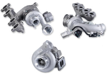
Assembly instructions for turbochargers
Specialist safety and installation instructions
Information on diagnostics
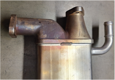
Thermal damage to EGR coolers
Causes, symptoms and prevention

Information on the product
Particle filter injection units
From the specialist in emission control
 on the turbocharger of an Audi A3 2.0 TFSI")
Information on the product
Electric recirculating air valves
Technology to prevent turbo lag

Information on the product
Nitrogen oxide / NOx sensors from the specialist in emission control

Information on diagnostics
Oil coolers
Malfunctions, causes, remedies

Information on diagnostics
Engine overheating: quickly find the root cause

Information on diagnostics
How suction jet pumps in the vehicle tank work

Information on the product
High voltage
Broken down vehicles and vehicles involved in an accident

Information on the product
High voltage safety rules – Working on electric vehicles safely
Measuring equipotential bonding, checking insulation resistance, recommissioning
")
Information on diagnostics
Whistling from a new EGR valve
Causes & solutions

Information on the product
High voltage – Qualifications and equipment
Dangers when working with high voltage