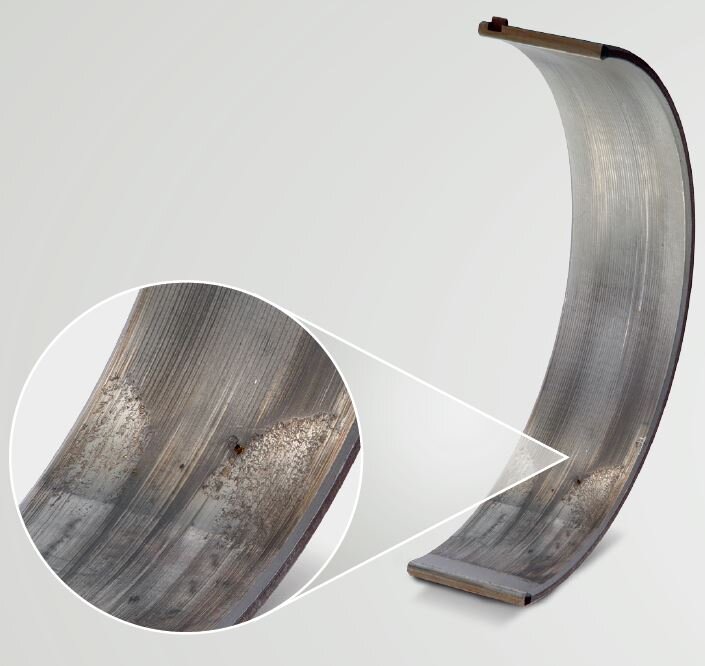
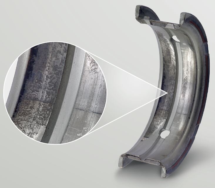
Cracks and nicks to the sliding layer
DESCRIPTION OF THE DAMAGE
- Fine cracks in the sliding layer identifiable: particularly oblique to the direction of movement – is often known as “bark beetle” as the damage symptoms resemble the feeding pattern of a bark beetle
- Often associated with edge wear and discolouration of the bearing surface

The engine bearing demonstrates signs of fatigue towards the relief in the form of cracks and initial nicks up into the brass layer.

One-sided edge wear on both bearing shells caused the fatigue of the galvanic layer and created the typical „bark beetle“ damage pattern.
Possible causes
Signs of fatigue, such as cracks and nicks on the bearing metal, are caused by dynamic overstrain. This can have various causes:
- Overstressing: if forces larger than the design allows for affect the bearing, material fatigue occurs – combustion defaults, such as knocking, increase the pressure on the piston and therefore also on the connecting rod bearing
- Lubrication gap dimensioned too small – a stable lubricating film cannot form: the lubricating film pressure rises in these locations and the surface pressure increases – this can be caused by misalignment, formal errors, errors in geometry or installation errors – inspection of the adjacent bearing can provide more information
- Poor oil quality or oil ageing: if unsuitable oil is used or the oil is not of a sufficient quality due to ageing, this can impair the formation of the lubricating film
- Vibrations: if the bearing is subject to alternating tensions due to vibrations, the risk of material fatigue increases
- High temperatures: material fatigue is accelerated by high temperatures since they reduce the strength of the bearing material
Remedy
- Check stress of the bearings – if necessary, a bearing that is more resistant to fatigue must be used
- Check for correct geometry of the crankshaft: dimensions, roundness, cylindricity, ripple, surface roughness
- Check the bearing line bore is correct: dimensions, roundness, cylindricity, surface
- Check the alignment of the main bearing bore (observe specified tightening torque of the bolts, cool engine sufficiently)
- Check connecting rods for angularity before installation
- Balance crankshaft during installation
- Only use oil recommended by the manufacturer and observe oil change intervals
- Ensure sufficient engine cooling