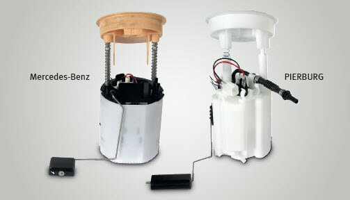
Mercedes-Benz in-tank modules
Replacement part solution for CLS- and E-Class
Back to search
Information on use
Mercedes Benz CLS and E-Class(W211): The sender unit and fuel module look different. Can I still install them? Do the hoses fit? How do I install them? These sender units and fuel modules may look different but in fact they can be interchanged without any problems. See below for instructions on how to install the parts.
Vehicles:
Mercedes-Benz
CLS 280, CLS 300, CLS 350 (CGI), CLS 500, CLS 55 AMG Kompressor, E 200 (CGI/Kompressor/NGT), E 230, E 240, E 280, E 320, E 350, E 500
Product: Fuel delivery module, fuel tank sender unit
Mercedes-Benz
CLS 280, CLS 300, CLS 350 (CGI), CLS 500, CLS 55 AMG Kompressor, E 200 (CGI/Kompressor/NGT), E 230, E 240, E 280, E 320, E 350, E 500
Product: Fuel delivery module, fuel tank sender unit
| PIERBURG no. | Ref. no. * |
|---|---|
| 7.02701.71.0 | A 211 470 14 94, A 211 470 29 94, A 211 470 41 94 |
| 7.02701.72.0 | A 211 470 14 41, A 211 470 39 94 |
The fuel delivery module and fuel tank sender unit which Motorservice offers for the vehicles listed above are different from the components installed by the vehicle manufacturers. These differences are partly due to patent law, and partly to a continuous improvement process:
- The fuel delivery module from Motorservice features carbon-carbon commutation and therefore conforms to regulation E10.
- The fuel delivery module from Motorservice has a lower current consumption with the same performance (4.4 bar at 13.5 V). Manufacturer: 162 W, 12 A Motorservice: 100 W, 7 A
- On the fuel tank sender unit from Motorservice, both return lines are joined into one line by a Y-connector.
Note:
Both the fuel delivery module and the fuel tank sender unit can be replaced individually or in pairs by the corresponding Motorservice components. This results in 4 different installation positions.
Please observe the following when replacing the parts:
The fuel delivery module (4) is located on the right-hand side of the saddle tank when viewed in the direction of travel (F).
The fuel tank sender unit (1) is located on the left-hand side of the saddle tank when viewed in the direction of travel (F).
The fuel delivery module (4) is located on the right-hand side of the saddle tank when viewed in the direction of travel (F).
The fuel tank sender unit (1) is located on the left-hand side of the saddle tank when viewed in the direction of travel (F).
The fuel delivery module (4) and fuel tank sender unit (1) are connected by electrical lines and fuel lines running through the narrowest point of the two sides of the tank.
The side of the fuel delivery module must also be opened for this reason when replacing the fuel tank sender unit.
The fuel delivery module (4) does not have an electrical connection in the flange cover. The power is supplied by means of the connector plug (2) on the fuel tank sender unit (1).
On the fuel tank sender unit from Motorservice, both return lines are joined into one line by a Y-connector (3).
Note:
Insert the fuel delivery module and fuel tank sender unit into the fuel tank so that the arrow on the flange cover points towards the marking on the fuel tank (Fig. 5).
Insert the fuel delivery module and fuel tank sender unit into the fuel tank so that the arrow on the flange cover points towards the marking on the fuel tank (Fig. 5).
When replacing the fuel tank sender unit (1), the piece of tubing (6) of the flow line must be shorted to approx 80 mm, and the 90° quick connector (5) enclosed must be mounted (Fig. 5). When ordering, make sure that you specify the exact engine type and any possible delineation by chassis number, engine ID code and model year!
Installation positions
Fuel delivery module: Vehicle manufacturer
Fuel tank sender unit: Vehicle manufacturer If no additional replacement has been performed, this is the installation position which you will encounter (Fig. 6):
Fuel tank sender unit: Vehicle manufacturer If no additional replacement has been performed, this is the installation position which you will encounter (Fig. 6):
- 2 return lines (2) clipped onto the fuel delivery module.
- Pressure line connected directly to the fuel pump by means of a 90° quick connector (3).
- Plug (1) of the electrical line leading to the fuel tank sender unit is located under the two return lines (2).
Fuel delivery module: Motorservice
Fuel tank sender unit: Vehicle manufacturer This installation position is encountered if you are only replacing the fuel delivery module (Fig. 7):
Fuel tank sender unit: Vehicle manufacturer This installation position is encountered if you are only replacing the fuel delivery module (Fig. 7):
- Connect pressure line to the straight piece of tubing (5) of the fuel pump with 90° quick connector (7).
- Clip 2 return lines (4) onto the fuel delivery module.
- Insert plug (6) of the electrical line leading to the fuel tank sender unit into the fuel delivery module.
Installation positions (continued)
Fuel delivery module: Vehicle manufacturer
Fuel tank sender unit: Motorservice This installation position is encountered if you are only replacing the fuel tank sender unit (Fig. 8):
Fuel tank sender unit: Motorservice This installation position is encountered if you are only replacing the fuel tank sender unit (Fig. 8):
- Insert plug (10) of the electrical line leading to the fuel tank sender unit into the socket under the return line (8).
- Pressure line connected directly to the fuel pump by means of a 90° quick connector (9).
- Clip 1 return line (8) into one of the two free supports on the fuel delivery module using a straight quick connector.
Fuel delivery module: Motorservice
Fuel tank sender unit: Motorservice This installation position is encountered if you are replacing both the fuel delivery module and the fuel tank sender unit (Fig. 9):
Fuel tank sender unit: Motorservice This installation position is encountered if you are replacing both the fuel delivery module and the fuel tank sender unit (Fig. 9):
- Connect pressure line to the straight piece of tubing (11) of the fuel pump with 90° quick connector (12).
- Clip 1 return line (14) into one of the two free supports on the fuel delivery module using a straight quick connector.
- Insert plug (13) of the electrical line leading to the fuel tank sender unit into the fuel delivery module.
* The reference numbers given are for comparison purposes only and must not be used on invoices to the consumer.
