Installation of engine bearings
Step by step instructions
Back to search
Information on diagnostics
When installing engine bearings, instructions should be followed precisely. Checking the dimensions and tolerances is after all particularly important for mounting. We provide an overview of which clearances and tolerances should be noted.
Preparation
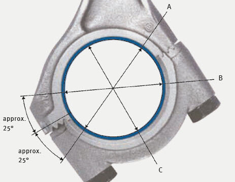
Diameter and roundness measurements on straight or inclined split connecting rods
The tightening specification must be observed for every machining and measurement process. As the diagram shows, two measurements are necessary:- Measurement on the installation bore (without bearing shell).
Note: Observed manufacturer's instructions if conrods have cracked! - Measurement with bearing shells inserted
For the bore dimensions, the tolerances stated in the catalogue apply.
Permitted taper and roundness:
| Diameter | Taper | Roundness |
|---|---|---|
| up to 25 mm | max. 3 µm | max. 3 µm |
| 25 to 50 mm | max. 5 µm | max. 5 µm |
| 50 to 120 mm | max. 7 µm | max. 7 µm |
Concentricity of main bearing counter bores on engine block
Permitted deviations: Overall concentricity of all bearing counter bores max. 0.02 mm Concentricity between adjacent bearing counter bores max. 0.01 mm
Permitted deviations: Overall concentricity of all bearing counter bores max. 0.02 mm Concentricity between adjacent bearing counter bores max. 0.01 mm
Installation
Note:
During crankshaft reconditioning, inspections for cracks must be carried out after aligning, after hardening and after grinding.
During crankshaft reconditioning, inspections for cracks must be carried out after aligning, after hardening and after grinding.
Final inspection of crankshaft
The shaft diameter is subject to the tolerances indicated in the catalogue. Carry out individual checks for compliance with roundness and parallelism tolerances. Permitted out-of-roundness max. one quarter of the shaft tolerance.
Maximum values for tapered, convex or concave ground shafts:
Maximum values for tapered, convex or concave ground shafts:
| Width | Tolerance |
|---|---|
| up to 30 mm | 3 μm |
| over 30 to 50 mm | 5 μm |
| over 50 mm | 7 μm |
Check for radial eccentricity
A concentricity check must be performed for each reconditioned crankshaft, especially after rehardening. The permitted radial eccentricity is measured supported on the outer main bearing journals.
Permitted misalignment of main bearing journal:
Adjacent journal: 0.005 mm
Total: 0.01 mm
These tolerances are standard values unless different figures are specified by the manufacturer.
Permitted misalignment of main bearing journal:
Adjacent journal: 0.005 mm
Total: 0.01 mm
These tolerances are standard values unless different figures are specified by the manufacturer.
Radius check
The radii must be dimensionally accurate as per the manufacturer's specification. Overly small radii result in crankshaft fracture. Excessively large radii lead to edge riding on the bearing.
Compliance with surface quality and dimensional tolerance specifications is particularly important with radius hardened bearing journals.
Compliance with surface quality and dimensional tolerance specifications is particularly important with radius hardened bearing journals.
Measuring the radius
If the correct radius gauge is selected, there should be no visible gap.Crankshaft hardness test
After grinding, the surface hardness of the crankshaft at the bearing journal must be over 55 HRC. If this surface hardness is not achieved, the crankshaft must be rehardened. Overly soft bearing journals result in bearing damage. Crankshafts with completely worn down bearing journals can no longer be used.
Attention:
Are the bolts OK?
Bolts with visible mechanical damage must be replaced. Bolts tightened by torque and angle permanently lengthen and can therefore no longer be used.
Are the bolts OK?
Bolts with visible mechanical damage must be replaced. Bolts tightened by torque and angle permanently lengthen and can therefore no longer be used.
Selecting the right plain bearings
Make a comparison with the removed bearing. This is the only way you can be sure that you have selected the right bearing from the catalogue. Motorservice supplies the bearing shells ready to fit, whatever the undersize grade. The bearings must not be remachined, unless otherwise specified in the catalogue.
“KS Plastic Gauge” measuring strip
Enables swift and accurate checking of the bearing clearance on cross-divided plain bearings. It is especially suitable for checking the clearance of crankshaft main bearings, conrod bearings and camshaft bearings in passenger car and utility vehicle engines.
“KS Plastic Gauge” is a thin, calibrated plastic strip, which is inserted in the oilfree bearing point to measure the bearing clearance. When the bearing cap is tightened, the strip is squashed widthways.
After the bearing cap has been released and removed, the resulting width of the plastic strip is measured and the bearing clearance determined using the supplied reference scale. The bearing clearance can be read in mm and in inches.
Measuring range: 0.025 to 0.175 mm
Scope of delivery: 10 measuring strips, measuring instructions and measuring scale
Note:
Oil on the shells. Use an oil can. A brush may transfer dirt particles from the oil container.
Oil on the shells. Use an oil can. A brush may transfer dirt particles from the oil container.
Tightening bolts
Follow the tightening specifications precisely, and check with a torque wrench. This is the only way to ensure the specified pressure and fit, secure seating of the bearing and correct clearance.
Correct axial clearance
The flanged bearing is designed with extra width for repair purposes. If you grind the crankshaft to match this bearing shell width or thrust washer thickness, you will adhere to the correct axial clearance. Information on engine-specific axial clearance can be obtained from the engine manufacturer.Attention:
Some repair grades of flanged bearings and thrust washers are designed with additional width allowance.
Some repair grades of flanged bearings and thrust washers are designed with additional width allowance.
To avoid damage at the first startup, we recommend in any case that the oil pressure system be filled with engine oil manually before starting the engine. This will ensure that any air that is in the oil pressure system will be removed and will guarantee that all the components will function safely from the beginning. In addition to the plain bearings, the hydraulic chain tensioners, camshaft phasing devices, hydraulic tappets and also engine components lubricated with engine oil such as turbochargers, fuel pumps, injection pumps and vacuum pumps benefit from this process as well.
Note:
This process is generally prescribed by many well-known engine manufacturers before starting a new or overhauled engine for the first time.
This process is generally prescribed by many well-known engine manufacturers before starting a new or overhauled engine for the first time.
