Damage to the pin retainers
Information on diagnostics
Why are the piston pins and the piston pin boss broken? Pin bore close to the circlips also damaged? Ends of the pin bores on both piston sides also worn out? Spherical wear visible on the front face of the piston? This article explains what can cause this.
General information about damage to the piston pin circlips
If the circlips fracture or their ends break off, this is due to excessive loads or improper handling while inserting the circlips. The circlips are only subjected to axial loads if the piston pin has an axial movement forced upon it. This occurs if the connecting rod is misaligned or is oscillating in a mostly asymmetric fashion, which causes the piston pin axis and the crankshaft axis to no longer be parallel. The piston pin then strikes in a very rapidly alternating sequence against the piston pin circlips and gradually forces them out of the groove. They are then forced on as far as the cylinder running surface, where they are worn away. Ultimately the circlips will break up. Some fragments become trapped between the piston and the cylinder, while other parts are thrown back and forth under inertia forces in the recess of the piston pin bosses, where they cause substantial material washout. It is also not uncommon for fragments to move through the inner bore in the piston pin right through to the other side of the piston, where they then also cause substantial damage.
Piston damage caused by broken piston pin circlips
Description of the damage 1
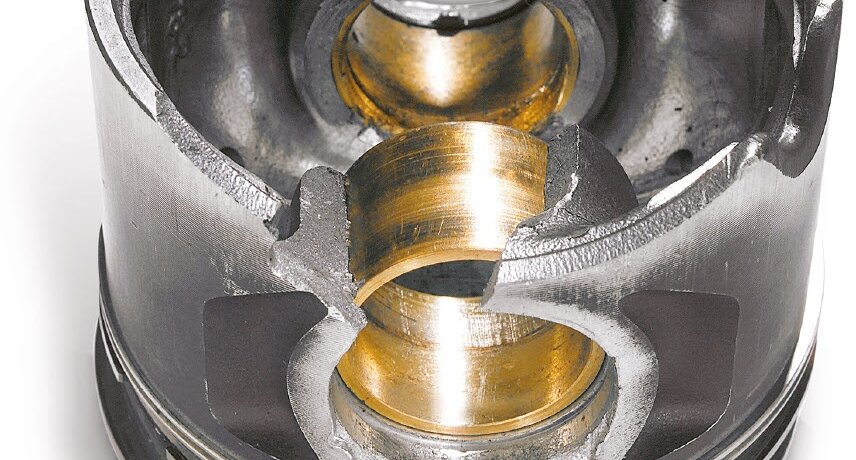
- End of the piston pin bore on both sides of the piston suffered serious damage, in some places as far as the ring zone (Fig. 1).
- Circlip jumped out of the retaining groove and broke into fragments.
- Second circlip damaged.
- Due to the lack of retention, the piston pin has wandered outwards towards the cylinder running surface.
- Front face of the piston pin worn to a convex shape due to prolonged contact with the cylinder running surface (Fig. 2).
- Asymmetrical running pattern of the piston.
Description of the Damage 2
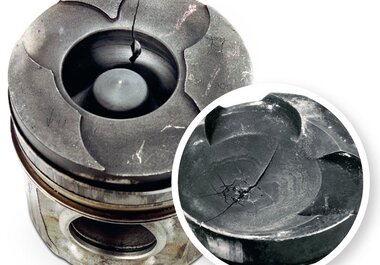
- Asymmetrical piston wear pattern (Fig. 4).
- Piston pin boss and piston pin broken (Fig. 5 and 6).
- Pin bore hammered out in the area of the circlips.
Damage Assessment
Whether as wire circlips or Seeger-type circlips, the piston pin circlips are only forced out or hammered out in operation by means of axial thrust of the piston pin. This is based on the requirement that the circlip has been correctly inserted and has not been damaged.
Axial thrust in the piston pin always occurs when the piston pin axis is not parallel to the crankshaft axis. This is the case when a bent connecting rod leads to the piston running at a considerable angle. The reciprocating movements result in alternating axial thrust, which effectively hammers out the circlip. Once the circlip has jumped out, it is then clamped between the piston pin moving in an outwards direction, the piston and the cylinder running surface.
There, it is worn away and finally breaks into several fragments. Within a short space of time the fragment inertia forces hammer into the piston material as the piston moves up and down (Fig. 2). Individual fragments also move through the hollow piston pin and cause corresponding destruction on the opposite side of the piston.
Possible causes for the Damage
- Axial thrust of the piston pin during engine operation caused by:
- Bending or twisting of the connecting rod.
- Connecting rod eye bored at an angle (axes not parallel).
- Cylinder axis not perpendicular to crankshaft axis.
- Excessive connecting rod bearing clearance, particularly in conjunction with asymmetrical connecting rods.
- Connecting rod pins not parallel with crankshaft axis (machining fault).
- Use of old or damaged circlips.
- Improperly installed circlips.

