Air Mass Sensors
Faults, Damage and Inspection
Information on diagnostics
Black smoke is escaping from the exhaust, the car has less power and is running in limp home function: These are the possible consequences if the air mass sensor (LMS) is sending incorrect signals. What are the causes? How does an air mass sensor work? What is on-board diagnostics (OBD)? What are possible diagnostic trouble codes? How can you test analogue air mass sensors? You will find answers to these questions and a wealth of additional information on air mass sensors in this article.
APPLICATIONS
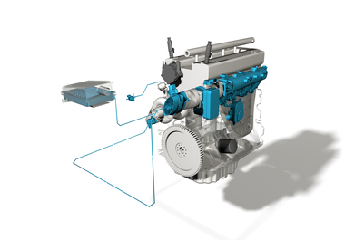
The air mass sensor precisely measures the air mass that flows into the engine (“mass air flow”). The signal from the air mass sensor is used to calculate the injected fuel quantity. In diesel engines, it also controls the exhaust gas recirculation. It is an important component in air supply and helps reduce exhaust gas. A defective or contaminated air mass sensor can convey incorrect input signals to the engine control unit, which then incorrectly operates other components. In turbo-diesel engines in particular, the stress on the air mass sensor is often so great that both air flow and air velocity are very high.
FUNCTION DESCRIPTION
The complete air mass sensor consists of a flow passage (tube), in which the intake air flows past the sensor unit itself.
NOTE:
Depending on application and vehicle, the air mass sensor is available as a single plug-in module, or fully integrated min a plastic tube. Both versions – with or without tube – are referred to as air mass sensors.
Older models have a hot-wire sensor element. Any contaminations on the hot-wire are burnt off by briefly heating it up after switching off the engine.
Newer models work with a film-like heating resistor on a mount. There is no burning-off process here. This hot-film sensor is heated to a constant temperature of approx. 120 – 180 °C above the intake air
temperature (depending on vehicle manufacturer).
The air cools the hot-film sensor as it flows in. The control electronics counter- balance this cooling by means of a heating current. This heating current is the measurement for the inflowing air mass. This method takes account of the density of the inflowing air. Pulsations and return flows can also be detected in newer designs with two separate measurement bridges.
FAULTS AND POSSIBLE CAUSES
Defective or contaminated air mass sensors can convey incorrect signals.
This can lead to:
- black smoke
- lack of power
- limp home function
POTENTIAL DAMAGE CAUSES ARE:
Leakages in the intake air system can allow dirt particles to enter with the intake air. These then hit the air mass sensor at high speed and destroy the delicate sensor element.
- Excess oil mist from the crankcase ventilation can oil up the sensor.
- Servicing errors, such as a dirty working environment when changing the air filter or using incorrect or poor-quality air filters, can also lead to dirt intake and damage to the air mass sensor.
- Splash water, such as during heavy rain, can enter the clean air side via the air filter and damage or contaminate the sensor. Salt water, such as from road salt and slush, increases this effect.
- Oil particles from oil-wetted sports air filters can damage or contaminate the sensor.
There are plenty of other factors that can cause an undamaged air mass sensor to provide incorrect signals:
- defective exhaust gas recirculation valves
- defective tank ventilation valves
- leakages in the intake air system
- blocked air filter
- damaged turbocharger (e.g. incorrectly calibrated wastegate)
AIR MASS SENSORS AND ON-BOARD DIAGNOSTICS (OBD)
Air mass sensors are monitored by the on-board diagnostics (OBD). Potential diagnostic trouble codes here can be:
- P0100 Malfunction in the air mass or air flow meter circuit
- P0101 Problem with the measuring range or power of the air mass or air flow meter circuit
- P0102 Air mass or air flow meter circuit too small
- P0103 Air mass or air flow meter circuit too large
- P0104 Misfire in the air mass or air flow meter circuit
Incorrect input signals from a defective air mass sensor can cause the engine control unit to incorrectly actuate other components. Any error messages that arise may therefore be a result of a defective air mass sensor:
- P0171 Mixture control (bank 1) system too lean
- P0172 Mixture control (bank 1) system too rich
- P0175 Mixture control (bank 2) system too rich
- P0401 EGR system – insufficient flow rate
- P0402 EGR system – excessive flow rate
SPORADIC FAULTS
Not every fault detected by the OBD leads directly to a malfunction indicator lamp illuminating. If a fault is detected in a driving cycle that influences the exhaust gas, it is saved as a “non-debounced” fault, meaning that the malfunction indicator lamp does not illuminate. The lamp only illuminates when the same fault occurs again during the next drive cycle or within a certain period. The fault is then designated as “debounced” (confirmed) and is saved as an OBD fault. Alongside the fault itself, other operating data and environmental conditions from the time of the fault are also collected and saved (“freeze frames”). The malfunction indicator lamp can go out again if the fault does not reoccur within a certain period. The data can be accessed using an engine tester or scan tool via the diagnostic socket in the vehicle:
- confirmed (debounced) faults in Mode 3
- sporadic faults in Mode 7
- operating data (“freeze frames”) in which a fault occurred in Mode 2
Even if the OBD indicates a sporadic fault on the air mass sensor, it does not necessarily mean that the sensor is defective. Moisture, oil mist or dirt often falsify the measuring results, which the OBD then interprets as an error. These sporadic faults can be caused by the aforementioned factors. For this reason, it is advisable to check these before fitting a new air mass sensor.
CHECKING ANALOGUE AIR MASS SENSORS
When diagnosing faults, begin by reading the diagnostic trouble code with an engine tester or scan tool.
PLEASE NOTE:
Although the OBD can detect a faulty part or function, it cannot determine the cause. Electrical faults in the wiring harness or in the component itself are usually saved as faults. They must be investigated using suitable test devices.
There are various ways to inspect the air mass sensor:
CHECKING THE VOLTAGE SUPPLY
- Disconnect the plug from the air mass sensor.
- Turn on the ignition.
- Measure the voltage at the plug.
 |
NOTE:
If these values are not reached, all affected lines and plugs must be checked for short circuits, interruption and transition resistances. |
|
NOTE: |
CHECKING THE LOW END OF THE SENSOR CURVE
Prerequisites:
- EGR system is functioning correctly.
- Air filter is clean.
- Maximum governed speed has been reached (as per emissions test data).
|
NOTE:
If the still-air output voltage is 1.00 ± 0.02 volts, the air mass sensor is almost always functioning correctly. If there is a risk that the measurementcould be falsified by air flows (wind), close both ends of the measuring tube using suitable means. If the output voltage is outside this tolerance, you should replace the air mass sensor. |
CHECKING REACTION
If a value of 1 volt is achieved, blow gently into the air mass sensor. The voltage value should now rise with the force at which you are blowing. If this does not happen, the sensor is defective and must be replaced.
MEASURING UNDER LOAD
- Start the engine. Set-point value (engine idling at operating temperature): 1.2 – 1.6 volts
- Increase the engine speed (burst of throttle) until the maximum governed speed is reached. You should achieve signal voltages of 3.8 to 4.4 volts.
The air mass sensor delivers a measurable voltage of around 1.0 to 4.4 volts between idling and full load. Replace the sensor if this does not happen.
Do not connect or disconnect any plug-in connections when the ignition is turned on. The peak stresses that arise as a result can destroy the electronic components.
|
NOTE: |