Camshaft adjustment for pollutant reduction
for almost 110 million vehicles
At high burning temperatures, exhaust gases (nitrogen oxides) are produced in the motor vehicle’s engine. Various effects can be achieved with the aid of adjustment or control of the camshaft in IC engines (petrol-powered engine, diesel-powered engine), such as reducing fuel use or internal exhaust gas recycling (EGR). 4/3 directional control valves are used as the valve controller. This article describes in detail how the adjustment system is constructed and the parts it consists of.
Camshaft adjustment is an established method of emission control. Depending on the engine speed, control valves (02) guide the flow of oil through different oil channels to the relevant chambers in the hydraulic camshaft adjuster (01).
As a result, the camshaft (03) is turned relative to the camshaft gear and the valve timing, i.e. the opening and closing points of the intake and exhaust valves, is changed.
The effects of this include:
You will find a list of the products currently available for delivery on the following pages. The range is continually being expanded.
As a result, the camshaft (03) is turned relative to the camshaft gear and the valve timing, i.e. the opening and closing points of the intake and exhaust valves, is changed.
The effects of this include:
- Improved operating behaviour under part load and full load
- Reduced fuel consumption
- Internal exhaust gas recirculation
- Dethrottling of the engine
- Reduced pollutant emissions
You will find a list of the products currently available for delivery on the following pages. The range is continually being expanded.
")
Background information
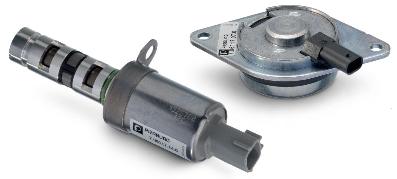
Control valves for camshaft adjustment are 4/3 way valves. They control the oil flow to working chambers A or B in the camshaft adjuster.
The central magnets are electromagnetic actuators and are a separate component. The actual valve body is part of the camshaft adjustment.
The central magnets are electromagnetic actuators and are a separate component. The actual valve body is part of the camshaft adjustment.
")
The camshaft adjuster is located on the end of the intake/outlet camshaft.
The rotor (04) with the oil channels to chambers A/B is permanently connected to the camshaft.
The stator (03) is connected to a ring gear, over which the timing chain runs.
The pressure in chambers A/B enables the rotor – and therefore the camshaft – to be adjusted so it is “early” or “late” relative to the stator.
This results in different lengths of time in which the intake and exhaust valve are simultaneously open.
This “internal exhaust gas recirculation” has an influence on the power and pollutant emissions of the engine.
Camshaft adjuster (schematic)
01 Chamber A
02 Chamber B
03 Stator
04 Rotor with oil channels to chambers A/B
The rotor (04) with the oil channels to chambers A/B is permanently connected to the camshaft.
The stator (03) is connected to a ring gear, over which the timing chain runs.
The pressure in chambers A/B enables the rotor – and therefore the camshaft – to be adjusted so it is “early” or “late” relative to the stator.
This results in different lengths of time in which the intake and exhaust valve are simultaneously open.
This “internal exhaust gas recirculation” has an influence on the power and pollutant emissions of the engine.
- When idling, minimal valve overlapping reduces the engine speed while optimising even running.
- For part load operation, the valve overlapping is set to achieve minimal emissions and low fuel consumption.
- At full load, the closing time of the intake valves is used to increase the torque and thus increase power.
Camshaft adjuster (schematic)
01 Chamber A
02 Chamber B
03 Stator
04 Rotor with oil channels to chambers A/B
")
")
Valve overlapping
05 Intake valve stroke
06 Exhaust valve stroke
07 Valve overlapping
05 Intake valve stroke
06 Exhaust valve stroke
07 Valve overlapping
Tags
Product groups
This might also interest you
