")
Water pumps from Audi/Seat/Škoda/VW
Danger of breakage: Note during fitting
Back to search
Information on diagnostics
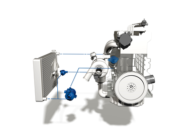
With many water pumps from Audi, Seat, Škoda and VW, the housing may break in the event of incorrect installation. Can the gaskets on the water pumps be oiled? What sequence has to be followed when tightening the bolts? You can find out how proper mounting works here.
| Ref. no.* | Pierburg no. | Vehicles |
| 06H121010A; 06H121026BA/CF/CQ/DD; 06J121026BG/P | 7.07152.08.0 | Many from Audi, Seat, Škoda, Volkswagen |
| 06H 121 008 F; 06H 121 010/026 AN/BE; 06J 121 026 G/L | 7.07152.35.0 | |
| 06H 121 026 AB/AF/AG/B/BE/BF/BP/CC/CD/CH/CM/CN/CP/DC/DN/N; 06J 121 026 A/F | 7.07856.08.0 | |
| 06H 121 026 CM/DB | 7.07856.37.01) | |
| 06H 121 026 CM/DB | 7.07856.40.01) |
1) Only available in the Asian market
With the water pumps listed above, there is a danger that the housing may break in the event of incorrect installation. The loss of cooling output may result in severe consequential damage, e.g. engine damage.
Causes for the damage symptoms include:
- Gaskets are contaminated with oil, e.g. due to oiling of the gasket or engine oil contamination in the surrounding area. This can cause the gasket to swell and the housing to break (Fig. 2 and 3).
- The sequence of the screw connection and the tightening torques have not been complied with.
Therefore, please always observe the assembly instructions enclosed.
 |
ATTENTION
|
 |
NOTE Gaskets may be lubricated with cooling liquid to make mounting easier. Only use new sealing rings. |
|
ATTENTION
|
|
NOTE Minor leakage of cooling liquid at the leakage hole is due to the design and does therefore not constitute reason for complaint. Depending on the version of the water pump, the temperature sensor** (Fig. 6) is either pre-assembled or included separately. |